
Section index · technical resources · 20/06/2026
Technical Datasheets
A datasheet is a dense page and almost everyone reads it in the wrong order. The headline output is at the top; the conditions that make it meaningful are in small type at the bottom.
This page sets out the standard blocks and what to check in each, as a companion to the documentation library.
A technical datasheet for a generating set is a dense page, and almost everyone reads it in the wrong order. The headline output is at the top; the conditions that make the headline meaningful are usually in small type at the bottom. Read from the bottom up and the sheet becomes far more useful.
The English-language sheets used across this market follow a broadly common structure, which makes side-by-side comparison possible once you know which line to look at.
The rated output block
This is the part that should be read with the duty classes in mind. A well-constructed sheet gives two or three figures for the same machine: emergency standby power, prime power and, sometimes, continuous power, each in both kVA and kW, at a stated power factor of normally 0.8 lagging. The gap between the standby and prime figures is usually around 9 to 10 per cent.
Under those figures sit the reference conditions: ambient temperature, altitude and sometimes relative humidity, following ISO 3046 for the engine and ISO 8528 for the set. If the sheet quotes 25 degrees Celsius at sea level and your plant room reaches 45 degrees at 1,200 metres, the headline figure is not the figure you will get. The corrections are worked through in the sizing method.
| Block | Key lines | What to check |
|---|---|---|
| Rated output | Standby, prime, continuous kVA and kW | Which class the quoted figure belongs to |
| Reference conditions | Ambient, altitude, power factor | Whether they match your site |
| Engine data | Model, displacement, aspiration, speed | Full model designation, not the brand |
| Alternator data | Model, insulation class, reactance | Class H insulation, winding type |
| Fuel consumption | Litres per hour at 25, 50, 75, 100 % | The load you will actually run at |
| Cooling | Rated ambient capability of the radiator | Often lower than the engine's limit |
| Dimensions and weight | Length, width, height, dry and wet weight | Access route and foundation |
| Sound level | dB(A) at a stated distance | Which distance, 1 m or 7 m |
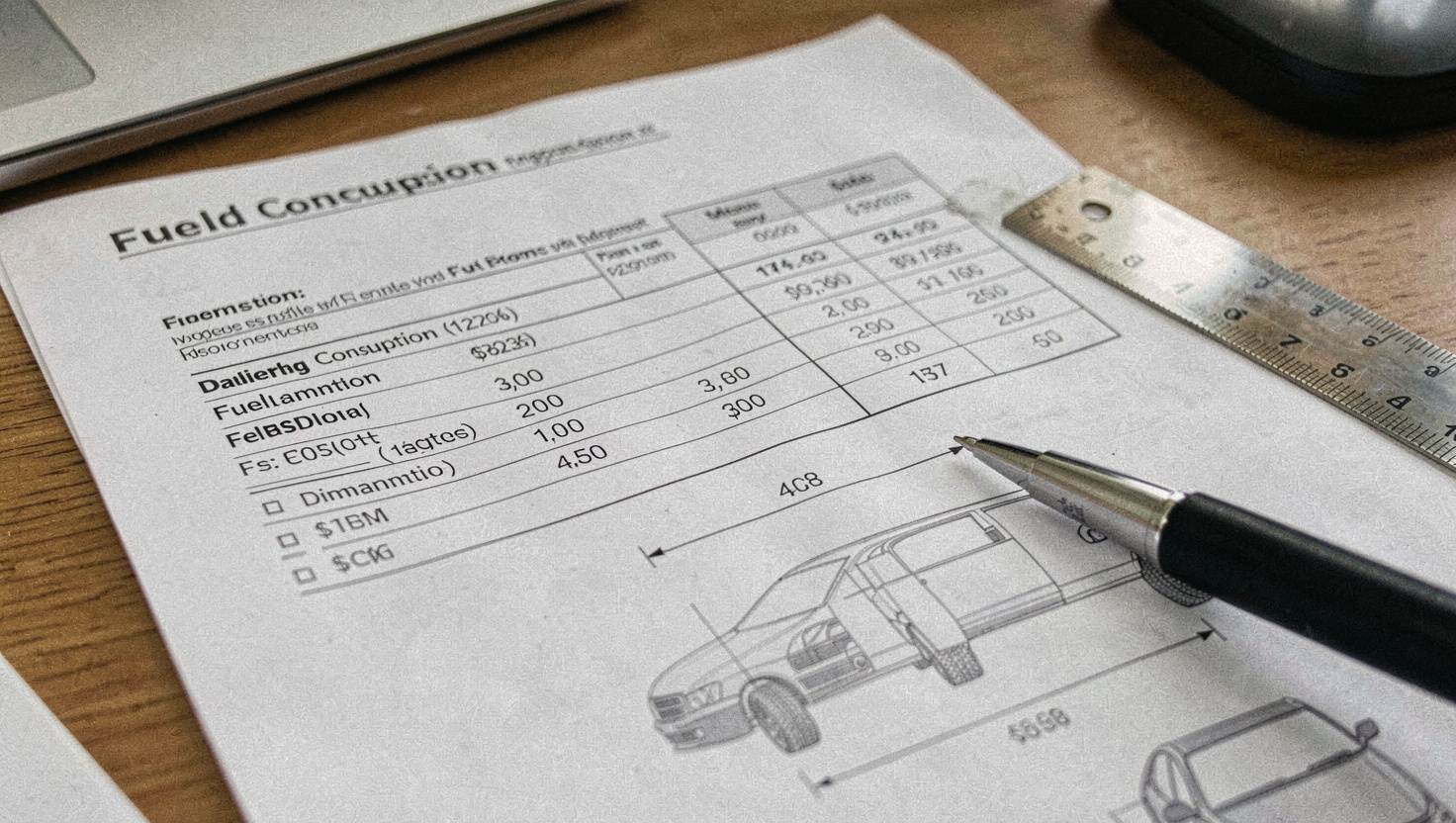
Fuel consumption, and the load that matters
Consumption is normally tabulated at 25, 50, 75 and 100 per cent of the rated load. The temptation is to read the 100 per cent figure and multiply. The useful figure is the one at the load the machine will actually carry, which on a prime power installation is commonly between 50 and 80 per cent, and the difference over a year is substantial.
Two warnings attach to these tables. They are measured at the reference conditions, so a hot site changes them. And they are measured on a specific fuel specification, which matters where local fuel differs, a question connected to the tank problems described in the fuel tank guide.
A sound pressure figure means nothing without the distance and the condition it was measured at. Sheets quote at 1 metre or at 7 metres, and occasionally at full load or at 75 per cent. A 7 metre figure looks around 15 dB better than a 1 metre figure for the same machine. Compare like with like or do not compare at all.
Enclosure and options
The enclosure section covers the canopy or container, its ingress protection rating under IEC 60529, the acoustic treatment fitted, the base fuel tank capacity and the autonomy that gives at a stated load. Autonomy is another figure that depends on the load assumed, so an eight hour tank at 75 per cent is a six hour tank at full load.
Options typically listed include the controller model, the circuit breaker rating, the battery charger, the jacket water heater and the anti-condensation heater. Of these, the jacket water heater is the one that decides whether a standby machine can take load quickly in a cold plant room, and it is worth confirming rather than assuming.
Using a sheet properly
The working method is short. Fix your own requirement first, using the sizing calculation. Then read each sheet from the reference conditions upward, correcting the rated output to your site. Then compare consumption at your actual load, not at full load. Then check the physical envelope against the access route. Only then look at price.
For the engine model designations that appear in the engine data block, the platform pages in the generator set section give the context, and the documents that should accompany the sheet in a project file are listed in the technical documentation library.
Read next
Fix the requirement before reading any sheet: sizing a generator set for your load gives the method and a worked example.
For the full document set a project should hold, and who produces each part, see the technical documentation library.
For the engine designations in the data block, the platform pages under the generator set section explain what each series covers.