Genset Digest / International Case Studies / Sintering cooling blower
Sintering Machine Loop Cooling Blower
Replacing a cooling blower on a sinter plant loop cooler is harder than buying a new one: the foundation, the ductwork, the noise limit and the shutdown window are all fixed before the specification starts. This profile sets out the requirements such a retrofit is normally written around.
Replacing a cooling blower on a sintering machine loop cooler is a harder brief than buying a new one, because almost nothing about the installation is open to negotiation. The foundation exists. The ductwork exists. The noise limit at the plant boundary exists and has usually tightened since the original machine was installed. And the shutdown window in which the change has to happen is measured in days.
This profile sets out the technical requirements that a retrofit of this type is normally written around. It describes a project type rather than a named engagement, because the constraint list is the part that transfers from one plant to the next.
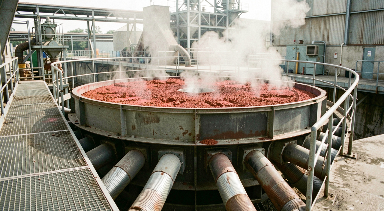
The duty that has to be matched
A loop or circular cooler receives hot sinter from the strand, typically in the range of 600 to 800 degrees Celsius, and has to deliver it cool enough for the downstream conveyors and screens, which usually means below about 150 degrees. The air requirement follows from the heat to be removed rather than from any duct calculation, and is commonly expressed per tonne of sinter, in the region of 2,000 to 2,800 cubic metres of air per tonne.
Because the cooler is a rotating bed with a variable depth and a variable permeability, the fan does not sit at one clean duty point. It has to hold its flow across a band, which pushes the selection toward a machine with a flat pressure characteristic in the working region rather than one with the highest peak efficiency.
| Requirement | Typical figure | Why it is set there |
|---|---|---|
| Airflow | 2,000 to 2,800 m3 per tonne of sinter | Heat removal to below 150 degrees C |
| Airflow tolerance | Within about 5 % of design | Bed depth and permeability vary |
| Static pressure | 3 to 8 kPa | Bed resistance plus ductwork |
| Noise limit | Commonly 85 dB(A) at 1 m | Plant hearing protection policy |
| Duty cycle | Around 8,000 h per year | Runs whenever the strand runs |
| Dust in the air stream | Abrasive fines | Blade wear becomes the service driver |
Airflow tolerance, and why it is written into the contract
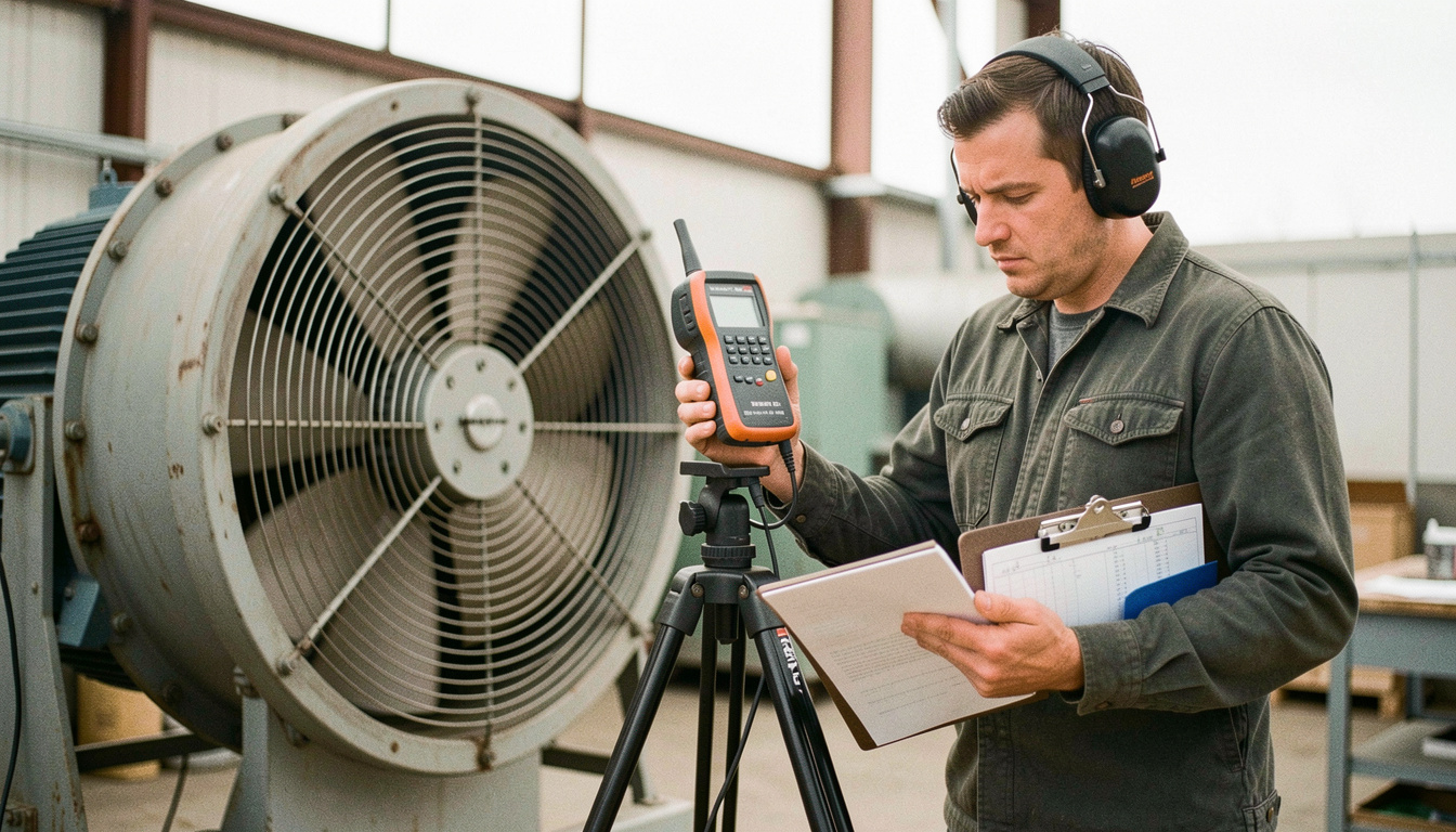
A tolerance of plus or minus 5 per cent on delivered airflow sounds generous until it is tested. Site acceptance is normally by measurement in the duct, and duct measurement is not easy: it needs a straight run of adequate length upstream, a proper traverse grid, and a correction for the actual gas density on the day. Plants that omit the straight run from the layout end up unable to prove the machine either way, which is a contractual problem rather than an engineering one.
The measurement discipline here is the same one that governs the low-pressure cooling duties described in the Stelmor blower page: you verify the air, not the motor current, because current tells you what the machine is absorbing and not what the process is receiving.
A retrofit specification should name the measurement plane, the straight duct length available upstream and downstream, and the method to be used. Without those three, an airflow tolerance is an unenforceable number and the acceptance test becomes an argument about instruments.
Noise, which is usually the tightest constraint
Noise limits on plant equipment are commonly written as a sound pressure level at one metre from the machine, with 85 dB(A) a frequent figure because it aligns with hearing protection policy inside the plant. Meeting it on a large fan is rarely a matter of the fan alone. The contributors are the impeller, the motor, the inlet, the discharge and the ductwork radiating structure-borne noise, and an acoustic enclosure around the machine does nothing for a duct that sings.
The practical answer is a package: inlet and discharge silencers sized for the actual spectrum, flexible connections at both ends, and an enclosure only where the residual requires it. On a retrofit the silencers have to fit the existing duct route, which is exactly the sort of constraint that eliminates otherwise suitable machines at the survey stage.
Foundation, envelope and the shutdown window
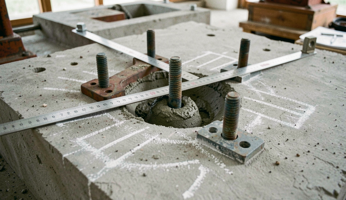
The existing foundation was cast for the original machine, with its bolt pattern and its mass. A replacement of a different frame size means either a new base plate that spans the old bolts or a foundation modification, and the second option consumes shutdown days that do not exist. The survey that establishes this, bolt centres, existing grout condition, available headroom for the crane, and the route the rotor will travel through the building, is the single most valuable day of the whole project.
Duty cycle closes the brief. A machine running roughly 8,000 hours a year is a continuous-duty machine, so the bearing arrangement, the lubrication method and the wear allowance on the blades all have to be specified for continuous service rather than for intermittent. The wear side of that decision is developed in the dedusting blower page, and the general sizing framework in the industrial blower section.
Read next
For the sizing discipline behind this brief, including system resistance and gas density corrections, read the dedusting blower page.
For the same measurement principle applied to a low-pressure cooling duty, the Stelmor blower page covers airflow uniformity on a rod line.
The export-project constraints around a brief like this, shipping, climate and parts distance, are collected in the international case studies hub, with the domestic profiles in the case studies section.